Tools and resources. Handy little things and links to libraries.
Here is a link to the Arduino DCC library from MynaBay I use in my projects : http://www.mynabay.com/arduino/2-uncategorised/14-arduino-dcc-monitor
And a link to TinyCad (free s/w) which I use to draw my schematic diagrams. : http://sourceforge.net/apps/mediawiki/tinycad/index.php?title=TinyCAD
The Arduino Keypad.h library can be downloaded from this link (and its use is documented there, too) : http://playground.arduino.cc/code/Keypad
Here is a KEWL link to a page explaining how to wire up the HD44780 LCD display : http://www.protostack.com/blog/2010/03/character-lcd-displays-part-1/
[NEW] If you want to develop your own DCC controller or use the DCC protocol, make sure to check out this site : http://bultez.fr/post/2013/02/07/first
(it originates from www.bultez.fr) and provides a full documentation for setting up a DCC controller. I was really inspired !!!)
[NEW] Likewise, if you want to control model trains using Märklin Motorola protocols (MM1, MM2, MM4, MFx, ...) then this is the place to be : http://sourceforge.net/p/ardurail/wiki/Home/
The very basic interface : linking DCC on the tracks to the Arduino
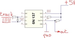
In order to be able to use DCC data from the track (controller) we will need to link the Arduino up to the track so it can read the bits and bytes that are superposed on the running current. This is done with just 5 components :
* a 6N137 optocoupler able to handle the high frequency DCC signal
* a simple 1N4148 diode at the input side
* a 1 K resistor at the input side
* 2 pcs 10 K resistor at the output side
Using these components, we link the Arduino to the actual track/controller and still ensure that there is no "hard-wired" connection, thanks to the optocoupler. We also match the input voltage to the Arduino maximum level of 5 Volts, whereas the DCC signal can go well over 20V dependin on your controller's and boosters' settings.
A simple but efficient way to amplify signals from Arduino's digital / PWM outputs
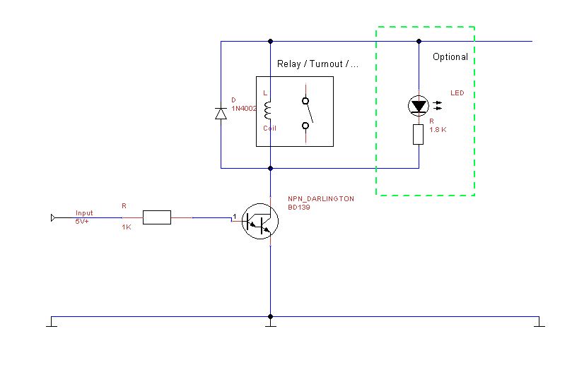
Often you will need to power "heavy" items through an Arduino output. This is not possible without a current amplifier. The very basic form is a simple NPN Darlington transistor with a feedback diode REVERSELY across the load (to prevent high voltage feedback through the transistor when switching off inductive loads such as coils or relays or inductive turnout-motors). The schematic below shows how it is done. If you want a visual indication, you can add an LED and an extra resistor to the "load" end.
By replacing the BD139 with another type (such as the TIP111) or a more powerful FET transistor, you can switch even larger loads.
On the other end, if you only need to switch a little light bulb or a number of LEDs, you may want to replace the BD139 with a low end, cheap BC-547 or a 2N222 NPN transistor, which can switch up to about 100 mA.
IMPORTANT NOTE : The voltage onthe secondary end (load end) can be different from the Arduino's 3.3 or 5V operating voltage, but .....
(1) ALWAYS make sure you use DC only
(2) ALWAYS connect the GND (negative wire) of both sides together !!!
Multiple output amplifiers using UN2003
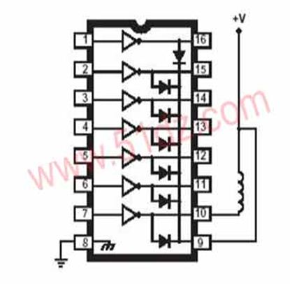
If you need multiple Darlington amplifiers for outputs, and you are limited in space, you can consider using the UN2003 IC.
This has 7 (seven) Darlingtons integrated which operate on common +, and switch to GND.
The each have a feedback Diode already across the input segment so there is no need for extra external components.
NOTE : LIMITED TOTAL CURRENT !!
Even though the UN2003 is generally rated at approx. 300 mA per output, you need to be careful not to overload it, because it has a Maximum Total power dissipation for the entire I.C. which is usually somewhere around 1200 mA. This means that when switching individual channels, you have no issue but when switching combinations of more than 2..3 channels, the IC will overload and show erratic behaviour or just stop working at all.
Link: http://www.alldatasheet.com/datasheet-pdf/pdf/202145/TI/UN2003A.html
Reference documents and data sheets for commonly used components.
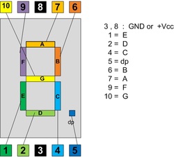
KW1-562 = 7 segments LED display
Comes in multiple colours, both Common Anode and Common Cathode series.
** KW1-562 Cxx is common CATHODE (negative)
** KW1-562 Axx is common ANODE (positive)
Comes in multiple colours, both Common Anode and Common Cathode series.
** KW1-562 Cxx is common CATHODE (negative)
** KW1-562 Axx is common ANODE (positive)
| kw1-562.pdf |
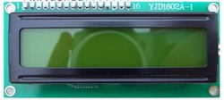
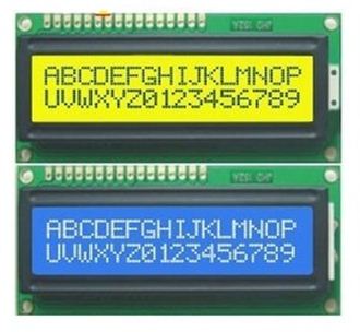
HD44780 LCD display 2 lines @ 16 chars each
Again, this comes in many variaeties and colours, but wiring is the same.
The Pinout is described below.
1= GND 2 = Vcc (5Volt) 3 = Vdd (display contrast voltage 0..5v)
4 = Register Select 5 = Read/Write 6 = Enable
7..14 =Data0 through Data7 (8 bits)
15 = Backlight + 16 = Backlight GND
Again, this comes in many variaeties and colours, but wiring is the same.
The Pinout is described below.
1= GND 2 = Vcc (5Volt) 3 = Vdd (display contrast voltage 0..5v)
4 = Register Select 5 = Read/Write 6 = Enable
7..14 =Data0 through Data7 (8 bits)
15 = Backlight + 16 = Backlight GND
| hd44780_lcd_display_how_to.pdf |
